IDEX offset of T1 on the far side from VAOC
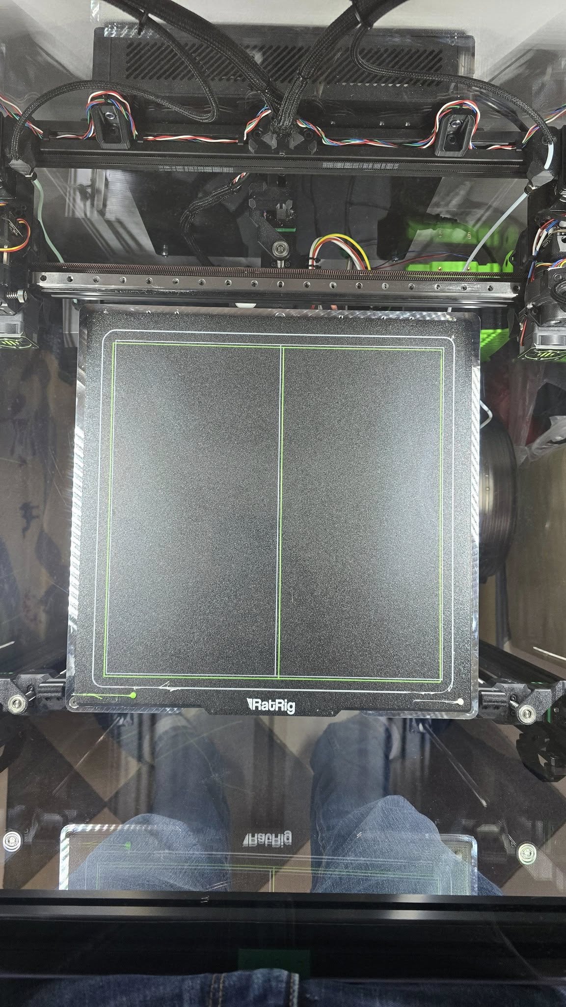
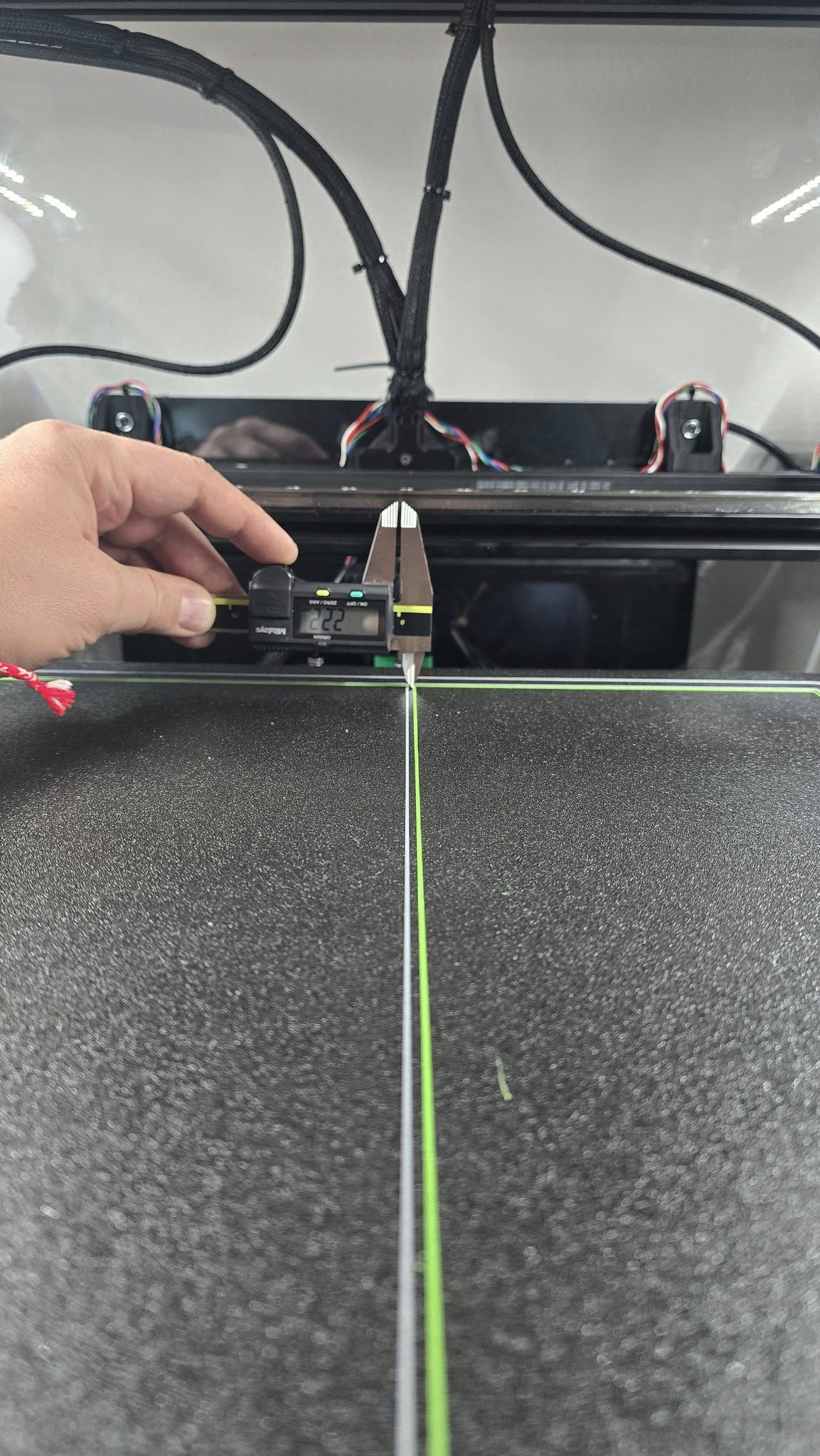
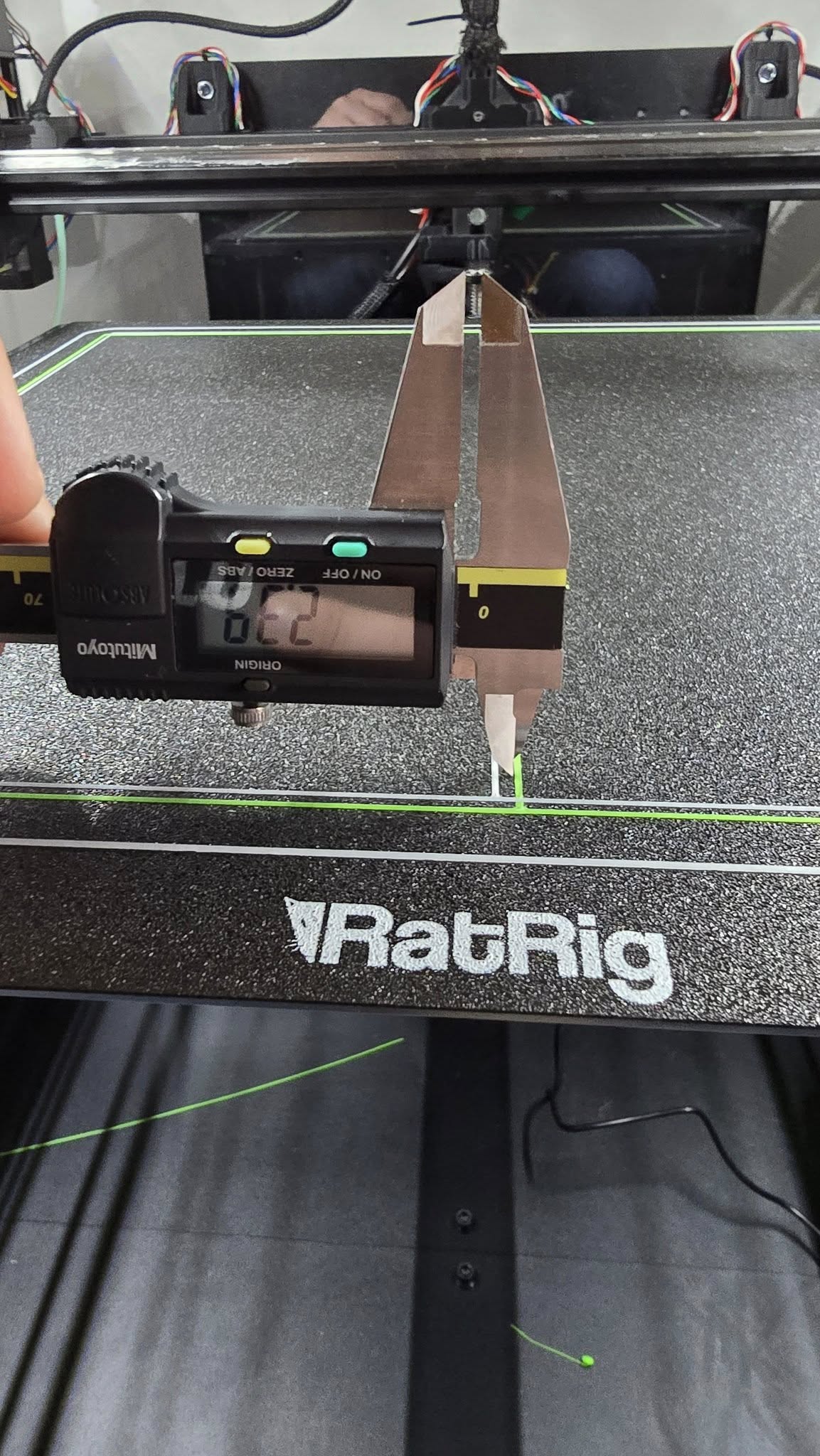
My issue is the prints coming out of my T1 is a kind of rotated regarding the prints from T0. Close to VAOC they're perfectly fine, but on the other side of the bed there is half a millimeter offset. What I did:
- Checked the rear plates with the motors (unscrewed and screwed again, to be sure they're flush to the profile).
- Adjusted the anchoring of the belts to the heads in order to make the front tensioners extend the same amount. It should make the length of both belts pretty much equal.
- Shaper graphs are good. Very low vibration percentage (under 2 for all). Y belt above 5700 MZV, X belts over 7500.
- The frame is quite well assembled. I've measured all diagonals and they have way less then 1 mm difference.
- The Y rails are parallel (as far as I could be precise with a ruler)
- The height map of my VCore 4 400 is with 0.080 mm tolerance when heat soaked, which also confirms the frame is good.
- The gantry is flush to the stoppers in end position.
- The diagonals of both 350 mm printed squares (in two colors) are equal. The skew value is zero. This also confirms the frame is straight.
No idea what to go for next. I bought an IDEX to be able print two filaments, otherwise I'd stick to my Voron, but one month later still no luck with setting that thing...
Any hints or ideas are welcome.
19 Replies
...One week later when I found some time and being told in IDEX thread it's a hardware issuтe:
...
- I've started fresh with removing most of the panels and checking on my mechanical stuff - frame, gantry belts. (miner moving of two non-important profiles on the frame, as they were out just a bit)
- Frame is square (diagonals measured, and all are within 1 mm tolerance)
- Gantry is squared with belts removed.
- All belts are absolutely equal. With belts tensioned, the gantry is flush to the end stops. All the tensioners (both CoreXY and Hybrid) are extending the same length from their "box" (difference less then 1 mm for all).
- Skew test done and results applied (little skew, diagonals are close in measurement).
- Shaper graphs are good in my understanding. All MZV acc is above 7700 and vibrations are close or less than 2%.
- RatOS configuration - redone. I've copy-pasted my additional configs only (led, sensors, etc.)
Results - absolutely the same, no mater I've changed, tuned and adjusted so many things. At least the results should vary a bit, but no...
With your lines drifting apart as you move away from the camera, your y axis belts need to be tightened/stretched more. Try a 1/4 turn on both sides and reprint to see if there is improvement.
correction: I see t0 is the line on the right(green) and t1 is the line on the left(white). Therefore the toolheads are drifting closer together. The Y belts are over stretched and need to be backed off a bit. The X and DC motors are not keeping up with how far the gantry is being moved by the Y motors.
They're not too tight and not too loos.
How did you come to that conclusion? If the Y belts are overstretched, the gantry will move further than intended moving T0 right and T1 left.
I'm having other printers with belts 🙂
I think I found my error. All these milion times I've missed the ENDSTOP_DC_CALIBRATION stuff
Ive got other printers with belts to. I understand what a good belt tension is. The tension may feel perfect and graphs may look perfect but if the distance of 100 teeth in the Y axis doesn't perfectly match the distance of 100 teeth in the X/DC axis(belt stretch), you will end up with your exact problem.
Nope. Back where I've started. Absolutely the same as before (in the previous image internal and external were printed with reversed T1 and T0, so the offset is in the same direction, actually). And this (almost 100%) same result is after all the changes done...
Just to remind what I did:
"What I did in the last weekend.
- I've started fresh with removing most of the panels and checking on my mechanical stuff - frame, gantry belts. (minor moving of two non-important profiles on the frame, as they were out just a bit)
- Frame is square (diagonals measured, and all are within 1 mm tolerance)
- Gantry is squared with belts removed.
- All belts are absolutely equal. With belts tensioned, the gantry is flush to the end stops. All the tensioners (both CoreXY and Hybrid) are extending the same length from their "box" (difference less then 1 mm for all).
- Skew test done and results applied (little skew, diagonals are close in measurement).
- Shaper graphs are good in my understanding. All MZV acc is above 7700 and vibrations are close or less than 2%.
- RatOS configuration - redone. I've copy-pasted my additional configs only (led, sensors, etc.)
- CALCULATE_DC_ENDSTOP redone.
Results - absolutely the same, no mater I've changed, tuned and adjusted so many things. At least the results should vary a bit, but no..."
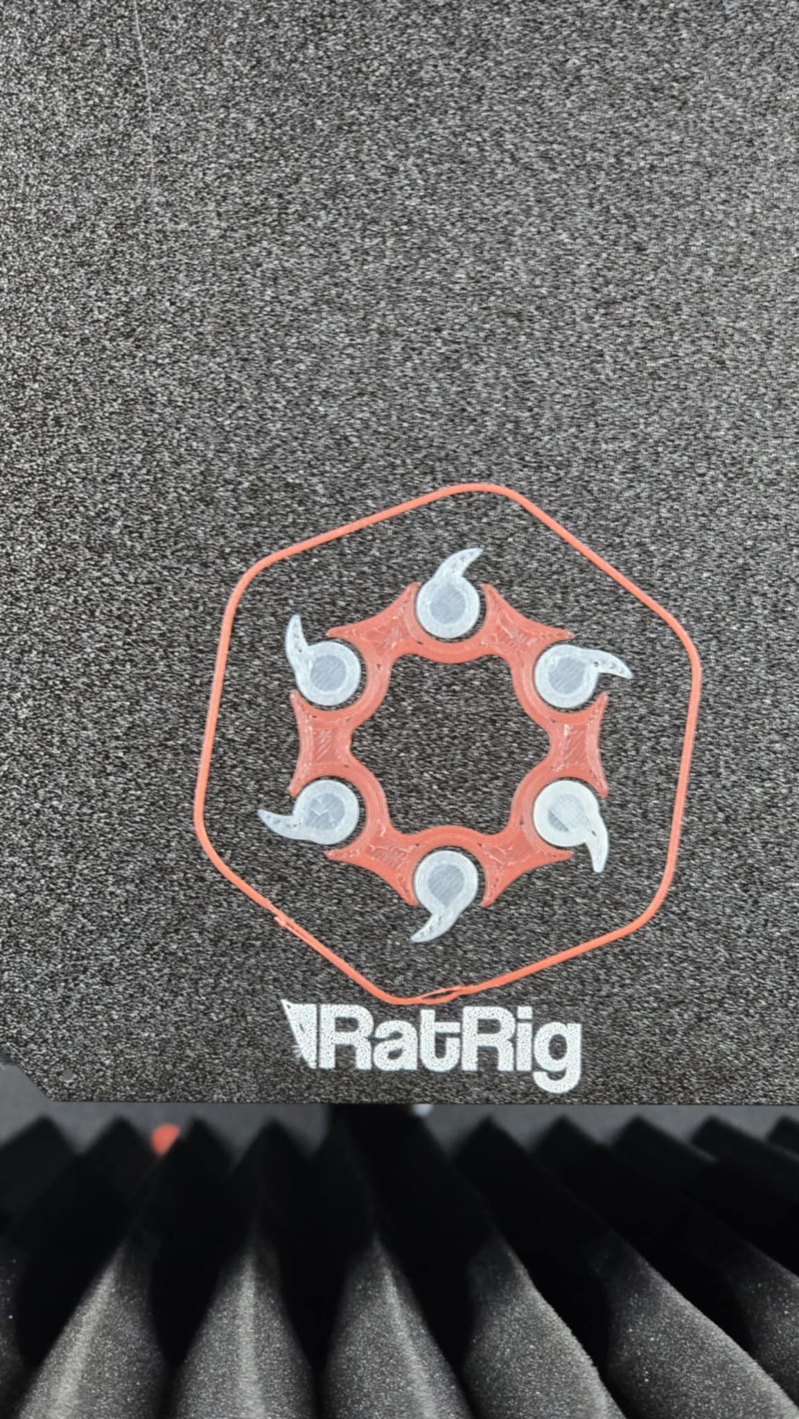
Did you try my recommendation?
I'm continuing with that tomorrow, but as I said, the belts have absolutely the same length. Gantry is flush to the end points and all the tensioners are sticking out absolutely equal. The only thing possible is small difference in tension, so that's what I'll try to change and see how it changes. But I've had enough for today and it's really frustrating and discouraging end at exactly the same point after a week of trying.
Give it a try. Do your lines test, measure the front and back, don’t touch x/dc, tighten or loosen both Y 1/4 turn equally(remember what you did), reprint, measure. If it got better, you’re going in the right direction. Worse, wrong direction.
I will, but I'm almost certain nothing would change.
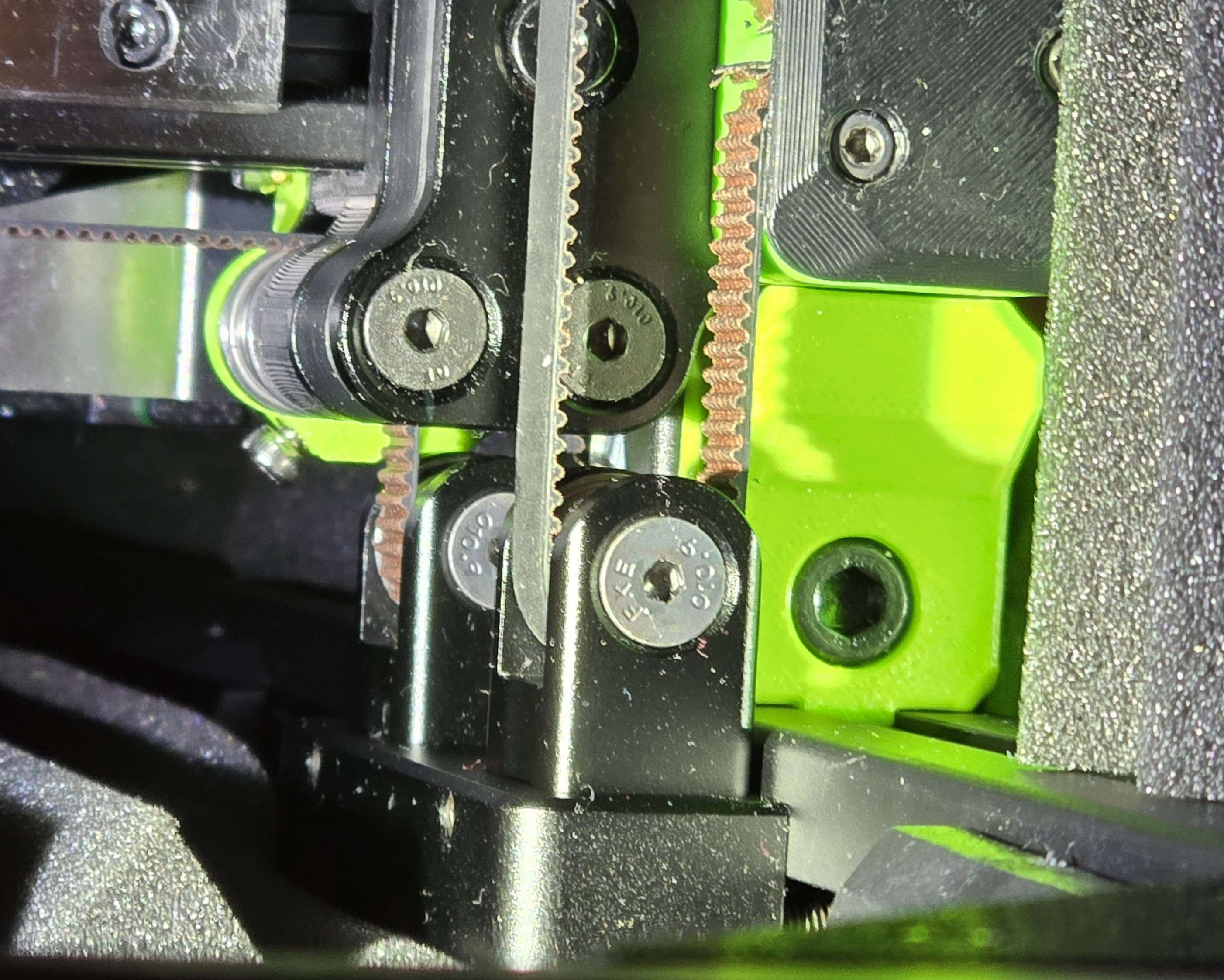
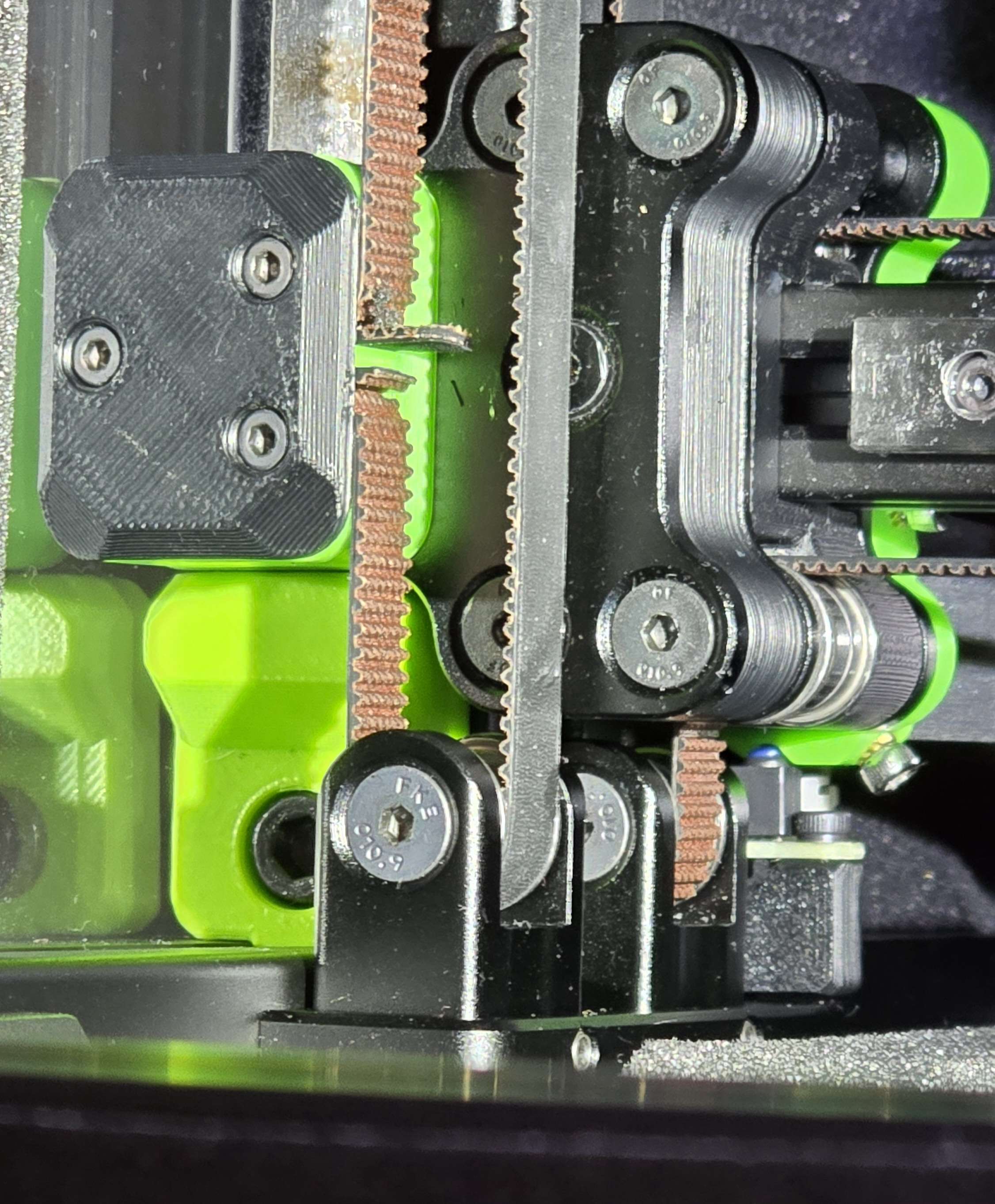
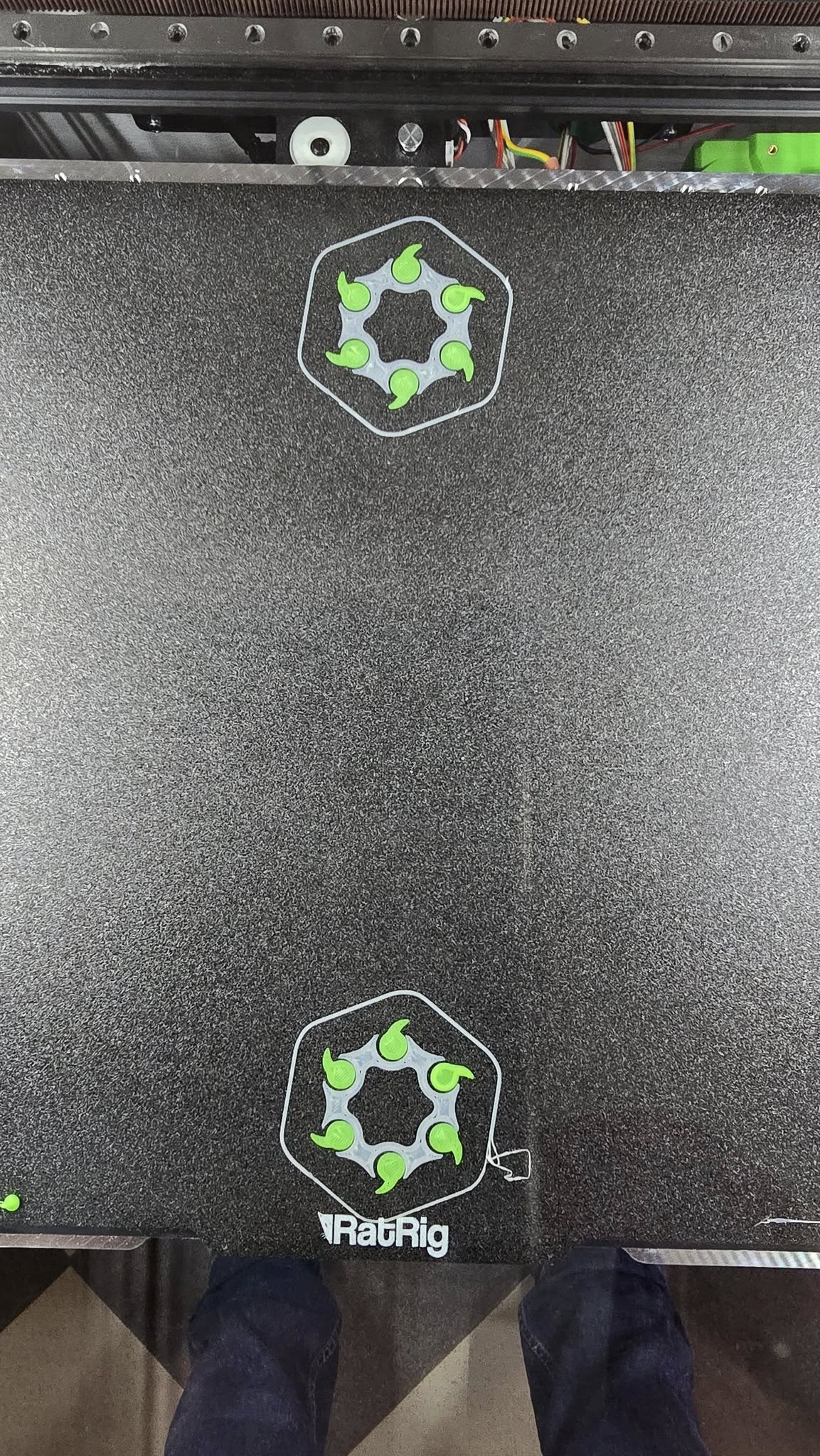
I'll start playing with it earliest tomorrow... In the meantime this is how my tensioners look. They're flush on the back side too.
How far the tensioners protrude from the box really doesn’t matter. You could have made one y belt 10mm longer and still achieved equal tension. Your IS graphs might be a bit wonky.
I don't understand that logic. If gantry is flush to both endstops (back and front), runs absolutely free before fitting the belts, frame is square, the tensioners are protruding the same length, would it be even possible the belts have different length?
I’m not saying your belts are not the correct length. I’m just saying don’t focus on how far the tensioner pulley is sticking out from the box. The X/DC pulleys will likely be different than both Ys.
I had the same issue https://discordapp.com/channels/582187371529764864/1342875001266634854 and loosening the Y-axis tensioners fixed it.
Hi people, Just reporting back.
For the last week I've managed to find some time and adjust the belt lengths by only playing with their anchoring to the toolheads. A little bit in, a little bit out and calibration tests and VAOC calibration after each print. Finally, all looks good enough.
I got fooled by the skew test with some wrong values I've measured or something else, which took me 2/3ths of all the time and parking going out of the limits... Changed skew to 0 and all went perfect. Absolutely the same diagonals on the big print and same offset of the line (0.05 mm difference).
Thanks for your help, as you advices made me realize what should I aim for...
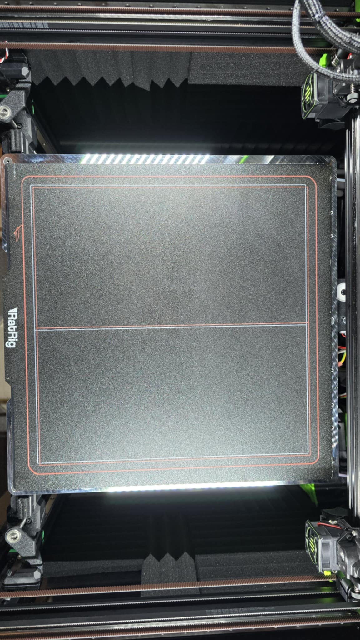
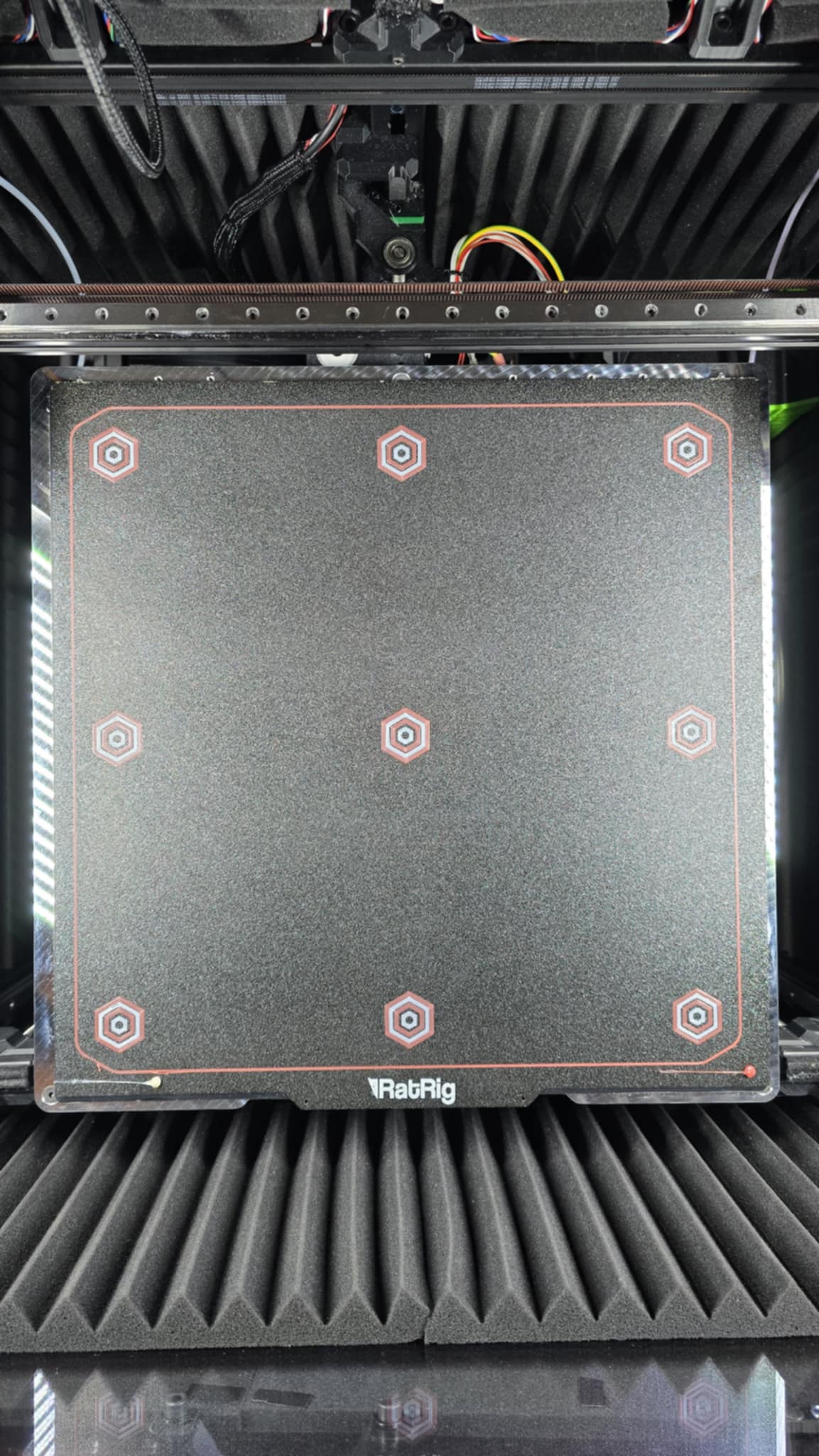
Just printed a skew test print, for the fun of it (I have value 0 for the skew in printer.cfg) and the two diagonals have only 0.02 difference, which could also be from uneven flow or whatever defect in the plastics....