Swapped out BL Touch for RatRig 5V Induction Probe
Since I was getting nowhere with the BlTouch issues, I decided to go the easy route and swap out the BLTouch for the RatRig induction probe.
Went to power on printer and got the standard error message: now I'm getting this,
Printer is not ready
The klippy host software is attempting to connect. Please retry in a few moments.
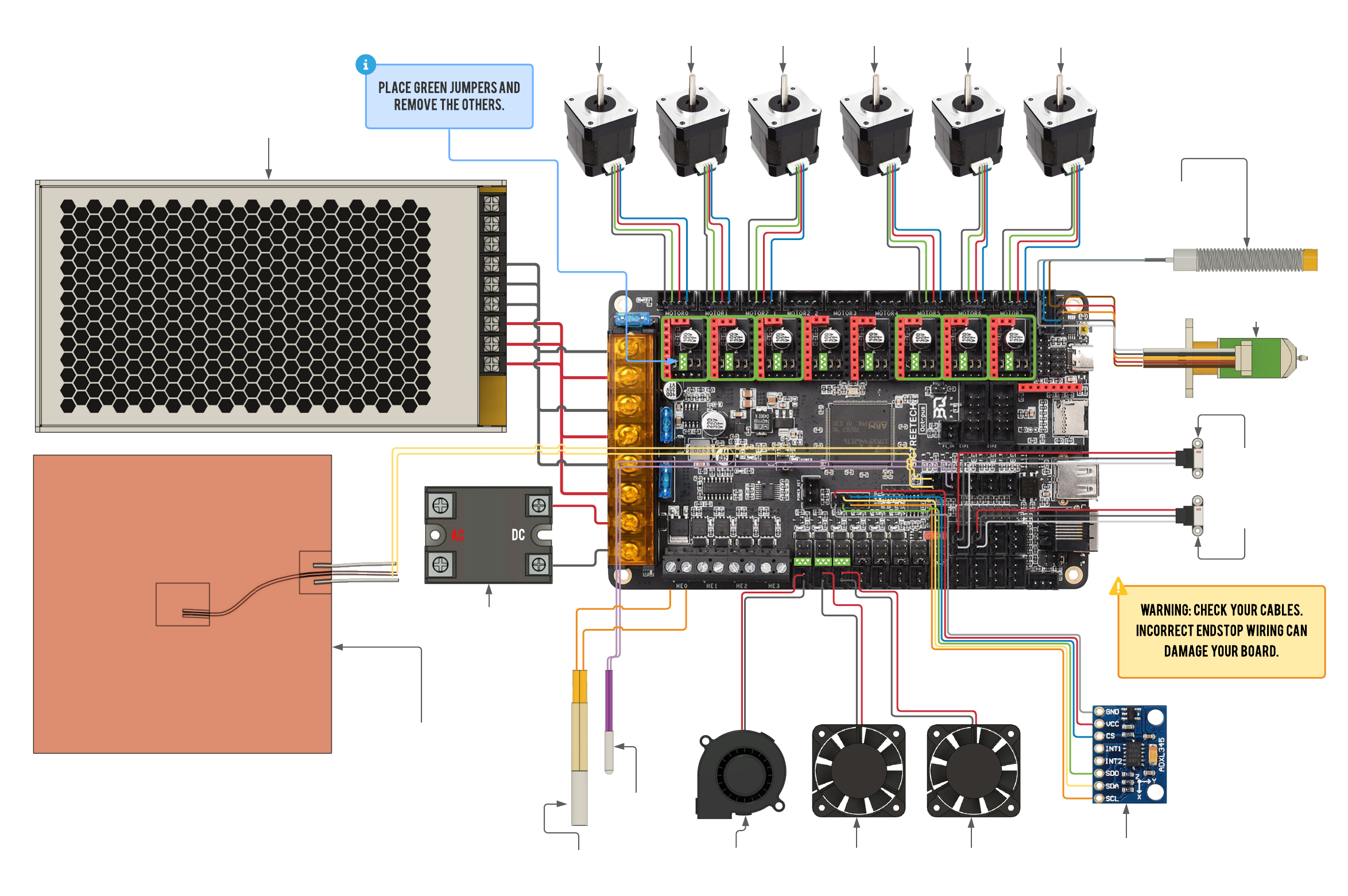
This was puzzling as I used the RatRig build docs to hook up the 3 wires to the BTT Ocotopus 1.1 board like the build diagram shows: BROWN, (space)BLUE, BLACK. Powered it up and thought I could go right into the configurator page and re-do my hardware, removing the BlTouch and adding in the inductive probe. Nope. Not happening.
I had to unplug the inductive probe from the board and restart. NOW, the printer comes up, but the probe wiring is obviuosly wrong, as it stopped the whole printer from booting up.
The wiring diagram on the RatOS page is incorrect for my build, as the page clearly shows a BTT Octopus Pro v1.0 board; I have a BTT Octopus Pro v1.1 board. https://os.ratrig.com/assets/images/octopus-11-wiring-19beb1b4b4719f7327a629b125c1dade.png FYI- The probe port was moved to a different location on the 1.1 board as depicted by the pinout diagram I uploaded & even this RatRig build guide image: So... I cannot get to the configurator page and re-do my hardware, the page just says configure; but does not show any of the configurator items. Also, who here has the correct cfg. entry and wiring for the RatRig inductive probe? Maybe I can edit the cfg files manually to get past this, but def not without the proper wiring ! Has anyone run into this one yet?
The wiring diagram on the RatOS page is incorrect for my build, as the page clearly shows a BTT Octopus Pro v1.0 board; I have a BTT Octopus Pro v1.1 board. https://os.ratrig.com/assets/images/octopus-11-wiring-19beb1b4b4719f7327a629b125c1dade.png FYI- The probe port was moved to a different location on the 1.1 board as depicted by the pinout diagram I uploaded & even this RatRig build guide image: So... I cannot get to the configurator page and re-do my hardware, the page just says configure; but does not show any of the configurator items. Also, who here has the correct cfg. entry and wiring for the RatRig inductive probe? Maybe I can edit the cfg files manually to get past this, but def not without the proper wiring ! Has anyone run into this one yet?

30 Replies
I used the guide to successfully hook up the superpinda to my octopus just fine; it has since been upgraded to use an EBB42 toolboard so I can't share a picture of how mine is setup
What do you mean by "can't get to the configurator page"?
If you share your printer.cfg we may be able to help
Oh, and a picture of how you have it wired up to double check that.
I believe that the images for the 723, 446 and 1.1 are the same on the RatRig site. My wiring is correct according to those images.


The wording in that first image confuses me, which board doesn't have the bltouch and probe pins multiplexed?
My thoughts exactly. After carefully parsing the sentence structure, I beleive they meant the 1.0 board only supported one type of sensor. The 1.1 board supports both, although the 1.1 board has a dedicated probe port with shared pinout for both BL Touch & inductive probe. I also found this thread from featuring none other than @miklschmidt Notice the images and discussion in that thread centered around the 1.0 board as the probe port is located in the upper right hand of the board. The v.1.1 has it relocated towards the lower center of the board near the ADXL port. So the question remains: do I need to solder a 4.7k resistor like they did with the 1.0 board? BTT has a lot to learn about proper documentation, IMO.
Inductive Probe not working (led always on) - Rat Rig Community [Un...
Hey guys, I need help getting a inductive probe from pepperl & fuchs to work.
Today I got an inductive probe from Pepperl & Fuchs (NPN NO) and I connected it to my octopus 1.1. Its connected according to the ratrig doku and the octopus pinning. But for some strange reason, the LED of the probe is always on. No matter if I touch metal or not.
...
Have you tested the probe directly to see if is working correctly?
Re-reading through this post I'm starting to wonder if you have it hooked up correctly but is internally broken and pulling the whole 5V line down and making the octopus brown out
I will try that, good thinking. I'd be a bit surprised if the probe was broken- It's brand new out of the package from RatRig...
me too, but its also weird that you lose mcu connection with it connected
I think we are getting closer...check this out- https://klipper.discourse.group/t/cant-get-inductive-probe-to-trigger/6522
Klipper
Can't Get Inductive Probe to Trigger
Basic Information: Printer Model: V Core 3.1 MCU / Printerboard: BTT Octopus Pro klippy.log (1.9 MB) Hello Again! I have a 5V Normally Open NPN inductive probe and I cant get Klipper to trigger. Plugged into Probe Socket, sense pin PB7. Have also tried plugged into endstop (PG10) Sense pin is logic high (3.2V) and pulled low when trigge...
Ok. I think have one of the issues sorted out. I originally cfg the board via the configurator tab in RatOS to use a BLTouch probe. This made several entries to the RatOS setting, pins and such as well as the printer.cfg. SO for all intents and purposes, the printer thinks it still has a BLTouch probe installed, due to the cfg settings. That presents a problem as the docs I have linked throughout this thread state you cannot use both a BLTouch and inductive probe, due to shared pin. While I have the inductive installed (currently unplugged now), all of the .cfg files still have references to the BLTouch which is totally wrong including the pull up pin and others. This is causing a conflict, as the board expects to see a 5 wire BLTouch, but instead the 3 wire inductive probe was plugged in. Think that's what was causing the board shutdown. I going to pull the board and try to reflash (sigh) and run the configurator again, as in start all over- but this time I'll choose the inductive probe from the list. This is the only thing I can think of that would cause the board lockup or shutdown. I need to have the correct entries for the inductive probe anyways, so that's where I should go next.
you should be able to just run the configurator again right?
If nothing else I've heard in here you can run it for a different printer, save, then go through configurator with the correct printer and settings, and save. That way there's nothing left from the old
That's what I thought...but that failed. I tried to go to the configurator page through the OS, but it dumps me at the Print History Page (images I UL above earlier in the thread). How can you get to the configurator page when it won't go there? Seems I saw someone else with that issue a week or so ago, but cannot find the thread or if it had a solution.
and clicking "setup wizard" in the top left doesn't help?
Tried that too... and the Setup Wizard tries to make me flash the board again first, but Auto/DFU are crossed out...meaning manual was the only way. Ugh.
Well...that didn't work. Redid the board, cfg's and all via setup wizard, plugged the probe into the board...and NO BOOT again. Power down, unplug probe and power up...just fine. So, @TheTik you may be correct that something has gone afoul with this BRAND NEW probe. FYI, the JST wire connections are all factory, I didn't make one of them, just re-arranged the pins in the shell according to the build diagrams. Almost out of ideas here, as I'm not sure how to test this probe. Don't know if it is PNP or NPN NO or NC, etc.
What probe and where did you buy it from?
UPDATE: "Don't know if it is PNP or NPN NO or NC, etc." The tiny print on the top of the probe says NPN NC, so that mystery is solved. The probes are the generic ones on the RatRig website and that's where I just bought them from approx 2 weeks ago. They were crazy cheap, so I bought 2. Now, I guess I know why? I'm going to test the other one in about 2 hours.
If this whole saga is because we were assuming the usual superpinda...
Swapped out the probe for the other one....same exact result. You cannot plug this probe into the probe port without it halting the printer. Unplug it from the board, printer interface comes up just fine. I'm not familiar with this SuperPinda saga you speak of... what's the deal with that? What did I miss now?
We thought you were using the SuperPinda, but you're not. Now that Im back at my computer, I'll try to figure out what is different about the probe you actually have
they both look to be NC and NPN at least
AND they have the same pinout/wire colors according to the docs on rr's site
Have you tested the probe with 5V and a multimeter off the printer? With it halting the whole board I really feel like its dragging the 5V line down
I'm getting leery of this board now that things are pointing back to the board. 2 Brand new probes right out of the package to me spells trouble with that probe port. Also, WHY the formerly working BLTouch wasn't working when plugged into same port. I did post quite a bit already about the weak opto coupler circuit that this port uses. Some say you need to use a different pin I/O, others say to boost the input voltage to the probe. Going to pissed if this board is FUBAR because of the probe port.
I'd still test the probe if you're able, but if you can get your hands on another octopus that would also narrow it down.
I just happen to have another brand new Octopus Pro 1.1 I just bought 2 weeks ago from RatRig. I'm not a big fan of SPOF (Single Point Of Failure), hence I always buy more than one of everything. My backups have backups.
smart!
I will need to RMA this other board, as it has had nothing but problems from day 1. Oh, and I stand corrected on my backup board- it is only a BTT Octopus v1.1 (NOT Pro 1.1) . The chipset is also slower- a 446 instead of the 723 I had on the first board. Since this board IS older and a known piece of hardware...any peculiar issues I need to be aware of? There is the issue of the heaters being turned on, saw that. Also the reason I bought the 723 Pro 1.1 in the first place. Whom can I contact here for the fastest RMA? I know Luke's name was mentioned, but I don't know who that is.
Only Luke here I know is lukeslaboratory
Creater of the Chube hotend
UPDATE: Woot! It lives! After swapping out the MCU for the backup unit, printer is ALIVE and kicking. Now to start calibrations, etc. Steppers are bit noisy in idle, will have to figure that out too. Go ahead and mark this thread as SOLVED, due to defective probe port on first MCU. FYI- I also remounted the BLTouch and it is working...FIRST TRY.

Woot!!